Where Vapor Condensers Are Applied


Standard Configurations and Purpose-Built Units

Condensing looks straightforward on paper until the real process conditions appear. Vapor streams almost never arrive as pure saturated vapor, noncondensable fractions are routinely higher than the data sheet assumes, and the allowable pressure drop is frequently far tighter than the geometry prefers. We evaluate the full condensing curve, actual gas loading, and expected turndown range, then match the metallurgy and construction to the service rather than forcing a stock design.

  • Sanitary & Clean Steam: Fully drainable 316L units for clean steam, evaporator vapor, and product-contact applications in food and dairy facilities.
  • Pharmaceutical & Bioprocess: ASME BPE hygienic designs featuring double tubesheets wherever a tube failure must not reach product or WFI.
  • Vacuum & Surface Condensing: Vacuum condensers and turbine surface condensers in which pressure drop and air in-leakage dominate performance.
  • Solvent & VOC Recovery: Condensing service that simultaneously improves recovery yield and reduces the load on downstream carbon beds or thermal oxidizers.

Chemical and pharmaceutical process equipment
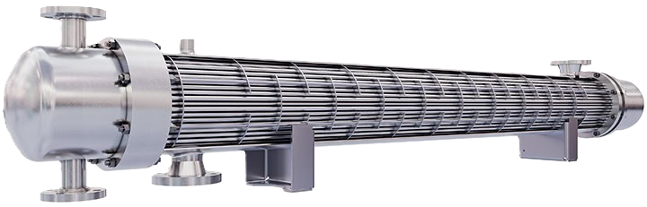
Food and beverage processing plant
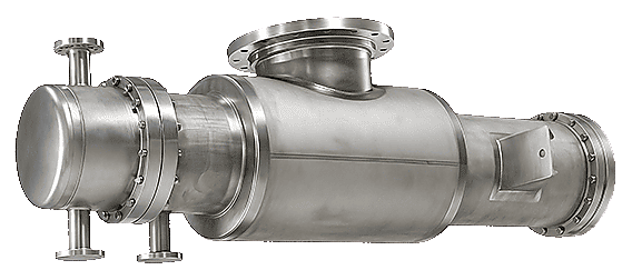
Industrial process and utility condensing equipment

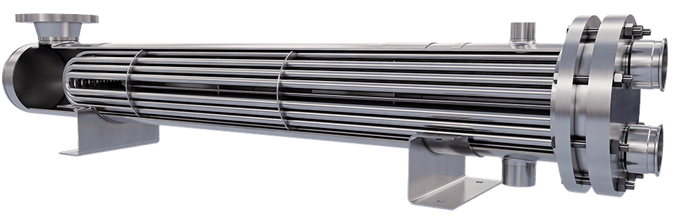
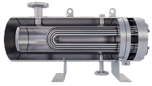
Stainless steel tube-bundle condenser for sanitary service

Practical Condensing Solutions

Condensing is the heat-transfer duty we are asked about more than any other. It is also the duty most frequently under-specified — not from neglect, but because a condenser offers more failure modes than a simple liquid-to-liquid exchanger. Noncondensable gas can blanket the surface. Condensate that cannot drain floods tubes from the outlet end. Multicomponent vapors condense across a temperature range that a single-point calculation cannot capture.

At quotation we focus on the variables that actually govern field performance: the noncondensable fraction present with the vapor, the pressure drop the process can truly tolerate, the elevation and drainage path of the unit, and the expected turndown. From those inputs we select the appropriate construction — shell and tube in the correct TEMA arrangement, air cooled when cooling water is limited, spiral for fouling streams, or plate when a close approach in a compact footprint is required.

Because we work with multiple established manufacturers rather than a single proprietary design, the recommendation can follow the process needs. If a particular construction better serves the duty even if it is less profitable for us, that is still the unit we will recommend. Discuss the application with an engineer at 1-805-484-2992.

Common FAQs

A vapor condenser is a heat exchanger designed to remove latent heat from a vapor stream so that the vapor returns to liquid form. Cooling is normally provided by water or air. Condensate is collected and either returned to the process, recovered as product, or directed to drain; any remaining noncondensable gas is vented to treatment or a vacuum system. These units appear on distillation columns, evaporators, reactors, sterilizers, dryers, vent lines, and steam turbines. The same fundamental function supports widely different goals — solvent recovery, vacuum maintenance, protection of downstream filters, or emissions compliance.

Noncondensable gas is far more often the root cause than fouling. Air in-leakage, nitrogen blanketing, inerts carried with the feed, or gas liberated from solution all migrate to the coldest surface and form a diffusion barrier that the condensable vapor must cross. That film creates far greater thermal resistance than the tube wall itself and collects precisely where performance is most sensitive.

The second frequent cause is inadequate condensate drainage. When liquid backs up from the outlet, active surface is progressively lost. The symptom looks like fouling from the control room but does not improve with cleaning. Both problems are design issues that are far less expensive to correct before the unit is fabricated than after it is installed.

No single style is optimal for every duty. Shell-and-tube remains the most versatile option, covering vacuum to high pressure, nearly any alloy, and vapor on either side. Air-cooled units eliminate the need for cooling water. Spiral exchangers tolerate fouling streams and deep vacuum and can be mounted directly on a column. Plate exchangers deliver the closest temperature approach in the smallest footprint on clean services. Double-pipe units suit small flows, high pressure, or very low hold-up requirements.

The practical selection criteria are volumetric vapor flow, allowable pressure drop, fouling tendency, and whether either side requires mechanical cleaning access.

Material selection is only the beginning. A true sanitary or pharmaceutical condenser is engineered so that every wetted surface can be cleaned and every drop of condensate can drain completely:

  • Surface finish: 316L wetted parts mechanically polished to a defined maximum roughness and passivated, because roughness controls both cleanability and biofilm attachment.
  • Drainable geometry: Sloped shells, low-point drains, and the absence of crevices or dead legs where warm condensate could remain between production campaigns.
  • Sanitary connections: Clamp fittings or extended tube weld ends instead of threaded or conventional flanged joints.
  • Double tubesheets: On duties where a tube leak could introduce utility fluid into product or WFI, a vented interspace converts a hidden contamination event into a visible indication.

For pharmaceutical applications ASME BPE further governs weld procedures, dead-leg ratios, examination methods, and the documentation package required for qualification. A unit that meets its thermal performance but arrives without the supporting paperwork cannot be qualified.

The more complete the data, the more accurate the first quotation will be:

  1. The vapor: mass flow and complete composition, including the noncondensable fraction. If the gas loading is unknown, say so — we will apply a realistic allowance rather than assume zero.
  2. Operating conditions: pressure, inlet temperature, and the required condensate outlet condition (including any subcooling).
  3. The coolant: fluid identity, supply temperature, available flow rate, and water quality if applicable.
  4. Constraints: allowable pressure drop on both sides, material or code requirements, hygienic standards, available space, and preferred orientation.
  5. Operating reality: expected turndown range, known fouling history, and the intended cleaning method.

Quote Request Form:

Questions?

1-805-484-2992

Quotes - Engineering - Sales